

Rotors
These are die-cast aluminum or Silumin alloy (Al-Si) squirrel-cage rotors.
Shafts (per CEI-IEC 72-1)
Made of standard C40/C43 steel (UNI 8373-7847).
They may be made of stainless steel for use with foodstuffs, or steel alloys, with standardized CEI IEC 72-1 dimensions or according to customer drawings.
The motor with double extension shaft, is only on request (with price list surcharge).
Tangs
These are made of C40 steel with dimensions standardized per CEI IEC 72-1.
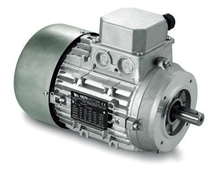
Frame (per CEI-IEC 72-1)
Die-cast aluminum with high mechanical capacity, good thermal conductivity, and very lightweight.
Frames are available in a version with standard tie-rods, with studs upon request.
Motor terminal board
For the B3 frame with feet, added in the terminal box, the terminal board is placed on top in standard production, or may be placed on the right or left side upon request.
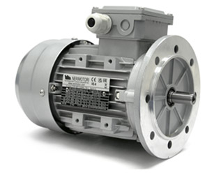
Flanges and shields (per CEI-IEC 72-1)
These are made of die-cast aluminum alloy, with standard dimensions per CEI-IEC 72-1 or based on customer drawings, reduced or enlarged.
For sizes 160 - 180 - 200, flanges B5 and B14 are in cast iron.
Caution: In flanges B14, seal the fixing holes not used; do not use very long screws or you may cause serious electrical hazards.
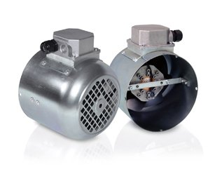
Cooling (per IEC 34-6 and CEI EN 60034-6)
Obtained by means of a two-way rotary fan with radial blades keyed onto the motor shaft IC 411.
Made of Latarnid 6, it has a high operating temperature of 100 °C.
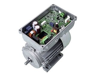
For applications with electronic controls such as inverters, assisted power cooling is available via an auxiliary cooling-type motor IC416, also in kit form.
Fan cover
Made of galvanised sheet metal, also available in plastic upon request for aggressive environments (MEC50 as standard).
Noise level (CEI EN 60034-9)
Sound pressure and power levels were measured on three-phase motors, one meter away from the machine, and weighted according to curve A (ISO R 1680). At 50 Hz for relative values at 60 Hz, this increases by an average of 4 dbA.
Vibration grade
Grade A (standard); others (B) upon request (CEI IEC 60034-14).
Per CEI EN 60034-9
Ventilation IC411 - Protection IP55 |
A-Sound pressure (LpA) - A-Sound power (LwA) |
|||||||
|
Motor size |
2 poles |
4 poles |
6 poles |
8 poles |
||||
| LpA [dB] | LwA [dB] | LpA [dB] | LwA [dB] | LpA [dB] | LwA [dB] | LpA [dB] | LwA [dB] | |
| 50 | 59 | 69 | 55 | 65 | 50 | 60 | 47 | 57 |
| 56 | 60 | 70 | 56 | 66 | 51 | 61 | 48 | 58 |
| 63 | 62 | 72 | 58 | 68 | 53 | 63 | 50 | 60 |
| 71 | 64 | 74 | 59 | 69 | 55 | 65 | 52 | 62 |
| 80 | 68 | 78 | 61 | 71 | 58 | 68 | 55 | 65 |
| 90 | 70 | 80 | 63 | 73 | 60 | 70 | 58 | 68 |
| 100 | 74 | 84 | 65 | 75 | 62 | 72 | 60 | 70 |
| 112 | 76 | 86 | 66 | 76 | 62 | 72 | 60 | 70 |
| 132 | 77 | 87 | 66 | 76 | 62 | 72 | 60 | 70 |
| 160 | 78 | 88 | 66 | 76 | 62 | 72 | 60 | 70 |
| 180 | 90 | 100 | 84 | 94 | 76 | 86 | 72 | 82 |
| 200 | 92 | 102 | 84 | 94 | 76 | 86 | 76 | 86 |
Indicative non binding values
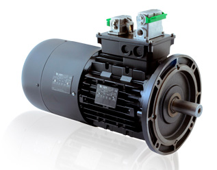
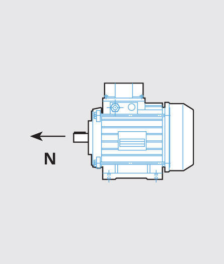
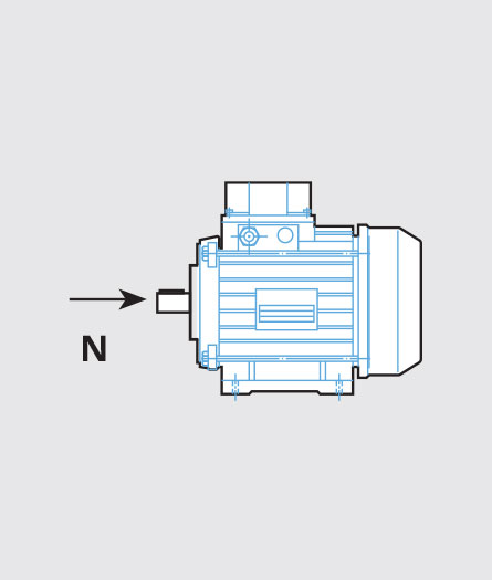
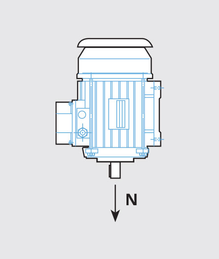
Available configurations (to specify when ordering)
Table shows the available motor configurations and installation positions per IEC 34-7.
Versions B3, B5, B14.
In general from MEC 71 to 200 reported feet, for specific requests contact the Commercial Dpt; from 100 to 200 it is reported in motor configuration.
.jpg)
IP ratings and housings
IP55 standard protection rating of the motors.
Special executions are possible for harsh environments with greater or specific protection except for other indications on motor rating plate.
Bearings
Front and rear ZZ radial ball bearings (sealed 2RS upon request), with two metal shields, prelubricated with lithium grease, with a temperature range from -10 °C to +110 °C.
Waterproof front bearings, C3 bearings with increased clearance, or bearings with special grease (-30°C to +140°C)/synthetic grease may be applied.
All are pre-loaded with corrugated tempered steel rings to eliminate residual clearance from the bearing.
Axially-free bearings; locked or with grease nipple upon request.
Size |
50 |
56 |
63 |
71 |
80 |
90 |
100 |
112 |
132 |
160 |
180 |
200 |
200-B5 |
|
Front |
6000-ZZ |
6201-ZZ |
6202-ZZ |
6203-ZZ |
6204-ZZ |
6205-ZZ |
6206-ZZ |
6206-ZZ |
6308-ZZ |
6309-ZZ |
6310-ZZ |
6310-ZZ |
6312-ZZ |
|
Back |
6000-ZZ |
6201-ZZ |
6202-ZZ |
6203-ZZ |
6204-ZZ |
6205-ZZ |
6206-ZZ |
6206-ZZ |
6308-ZZ |
6309-ZZ |
6310-ZZ |
6310-ZZ |
6310-ZZ |
Axial Loads
The table below shows the maximum applicable axial loads [N] at 50 Hz, calculated for a running life of:
Reduce values by approximately 6% for 60-Hz motors
* To be intended as indicative and not guaranteed
Size |
Horizontally-mounted motors |
Vertically-mounted motors |
||||||||||||||
|
|
|
|
|
|
||||||||||||
|
|
Speed (min -1) |
Speed (min -1) |
||||||||||||||
|
|
750 | 1000 | 1500 | 3000 | 750 | 1000 | 1500 | 3000 | 750 | 1000 | 1500 | 3000 | 750 | 1000 | 1500 | 3000 |
| 50 | - | - | 120 | 100 | - | - | 120 | 100 | - | - | 100 | 80 | - | - | 110 | 90 |
| 56 | 230 | 200 | 160 | 120 | 230 | 200 | 160 | 120 | 220 | 160 | 120 | 100 | 230 | 170 | 130 | 110 |
| 63 | 320 | 300 | 250 | 200 | 320 | 300 | 250 | 200 | 300 | 290 | 240 | 190 | 320 | 310 | 260 | 210 |
| 71 | 380 | 360 | 300 | 240 | 380 | 360 | 300 | 240 | 365 | 345 | 285 | 230 | 395 | 375 | 315 | 250 |
| 80 | 480 | 430 | 370 | 300 | 880 | 730 | 600 | 600 | 450 | 400 | 340 | 280 | 510 | 460 | 400 | 320 |
| 90 | 650 | 600 | 510 | 400 | 950 | 900 | 810 | 800 | 600 | 550 | 470 | 360 | 700 | 650 | 550 | 440 |
| 100 | 850 | 750 | 580 | 500 | 1150 | 1050 | 1000 | 1000 | 770 | 670 | 500 | 430 | 930 | 830 | 660 | 570 |
| 112 | 1300 | 1250 | 950 | 700 | 1150 | 1050 | 1000 | 1000 | 1200 | 1150 | 850 | 620 | 1100 | 1000 | 850 | 680 |
| 132 | 1800 | 1700 | 1350 | 800 | 2000 | 1800 | 1400 | 1400 | 1600 | 1500 | 1150 | 650 | 1500 | 1300 | 1100 | 850 |
| 160 | 2300 | 2000 | 1600 | 1400 | 2800 | 2500 | 2200 | 2200 | 2000 | 1700 | 1400 | 1300 | 2000 | 2000 | 2000 | 1500 |
| 180 | 2600 | 2300 | -1800 | 1600 | 3300 | 3000 | 2500 | 2500 | 2200 | 1900 | 1500 | 1400 | 3000 | 3000 | 3000 | 2500 |
| 200 | 3400 | 3000 | 2400 | 2400 | 4200 | 3800 | 3200 | 3200 | 2800 | 2500 | 2000 | 2000 | 4000 | 4000 | 3800 | 3500 |
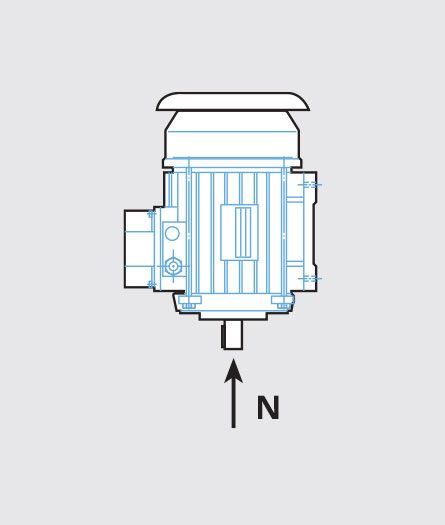
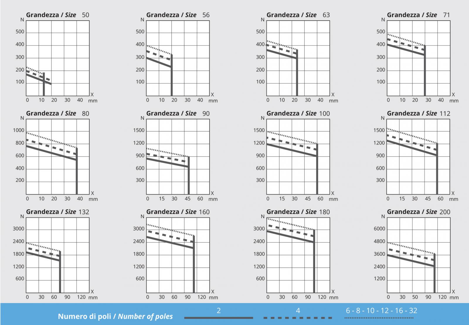
Radial Loads
These diagrams make it possible to determine the maximum applicable loads [N] based on measurement X, calculated for a bearing running life of:
* To be intended as indicative and not guaranteed
Radial load when using pulleys and belts
If the motor is coupled by belts, make sure the radial load on the shaft does not exceed the maximum allowed values.
This may be checked using the following formula where:

F = radial load in N
P = power in kW
n = motor rpm in 1st
D = pulley diameter in meters
K = - 2 flat pulleys with belt stretcher roller
- 2.25 for trapezoid groove pulleys
- 2.25 ÷ 3 for heavy duty and other pulleys