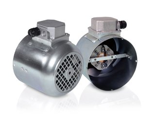


General notes
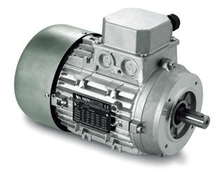
These use spring-pressure brakes, firmly spliced onto a cast iron shield at the back of the motor.
In the S line, the shield may be aluminum.
Powered by direct current or alternating current, with negative action (positive upon request).
The braking action appears in the absence of power supply to the brake coil; these are therefore negative brakes except positive brake.
The insulation class of these brakes is “Class F”.
For single-phase, three-phase and dual-polarity motors, these faithfully follow the specifications already illustrated in this catalogue from a mechanical and electrical standpoint, with the exception of axial dimensions which increase due to the presence of the brake.
The lining of our brakes is asbestos-free, per the most recent EEC Directives in terms of Workplace Hygiene and Safety.
All brake assemblies are protected against atmospheric aggression by painting and/or heat galvanizing.
The parts most subject to wear are treated in special atmospheres that provide considerable wear resistance to the parts.
As standard, the shaft in self-braking motors features a rear hexagonal end.
N.B.: Atex Brakes for Zone 2/22 are only Parking Brake Duty.
Supply voltage
The standard supply voltages for the brakes are 230/400V ±5%/50 Hz for three-phase brakes (direct mains if brakes are standard, separated mains if they are for inverter), and 230V ±10%50/60 Hz for direct current brakes on the AC side of the brake power pack.
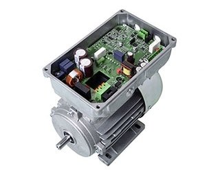
Direct current brakes require a power pack in order to operate on an AC mains.
Special supply voltages are available upon request: for AC brakes, in the range 24 ÷ 690 VAC with frequencies of 50/60 Hz; for DC brakes, in the range 24 ÷ 295 VDC.
Installation site
The standard electrical protection rating for the brake is IP54, while the mechanical protection for the brake installed on the motor is IP54 Choosing the brake protection requires special attention based on the user environment: in places with misted water or high humidity, where dust is present in the air, or where oily atmospheres are present, additional mechanical protections must be installed as specified below (dust protection ring).
DC brake intervention times
The power packs may be chosen based on the desired braking times. Due to the inertial rotation of the motor, the brake terminals receive energy even after the mains power supply is shut off (if connected via terminal board).
This causes a braking delay that may be undesirable.
To eliminate this delay, the brake power supply circuit may be interrupted directly on its coil, thereby preventing the inertial energy of the motor from keeping the brake powered. The tables below offers the parameters for choosing the desired braking times.
Noise levels
The brakes used for motor sizes we produce remain well within the limits set by the EEC Directives in terms of Worker Protection against the risk of exposure to noise at the workplace.
This limit may be briefly identified as 140 dB for nonweighted instantaneous acoustic pressure.
Parts available upon request
Hand release lever:
moving the level towards the fan cover of the motor releases the brake, making it possible to use the hexagonal Allen wrench to move the unit.
A through hole is available on the fan cover side to access the head of the motor shaft, containing the hexagonal movement hole.
Positive-action brakes (power supply upon request):
in which the braking action is exercised when the brake coil is powered; the motor is free if the brake is not powered.
Separate brake power supply:
achieved by means of an auxiliary terminal board, with fixed brake coil terminals, located inside the motor terminal box.
Increased terminal boxes for IP65 self-braking motors are available upon request.
Separate power supply is standard for 2-pole, self-braking and servo- ventilated motors, motor voltage: 400 V/690 V; brake voltage: 24 V, IN series.
In brake motors with 400V / 690V power, the brake is to separate power supply in Volt 230V / 400V three-phase (AC).
If the brakes are working at variable speed, do not exceed the limits indicated in table 15 / 16 / 17 / 18 (for information ask at UT Neri Motori)
Increased braking torque:
upon request, it is possible to have increased braking torque over the standards listed in the following tables.
Generally speaking, it is possible to have a braking torque used on the next larger motor size.
Increased protection levels:
We can supply other two protection levels, available upon request:
FP brake for lift:
the table below shows performance (braking torque / maximum speed) of the electromechanical brakes series FP, according to the requirements prescribed in paragraph 12.4.2. oh the UNI EN 81-1 / 1999.
Motor size |
Nom. Braking torque [Nm] |
Speed max [min-1] |
|
71 |
8 (2x4) |
3600 |
|
80 |
16 (2x8) |
3600 |
|
90 |
32 (2x16) |
3600 |
|
100 |
64 (2x32) |
3600 |
|
112 |
120 (2x60) |
3600 |
|
132 |
160 (2x80) |
3600 |
|
160 |
300 (2x150) |
1800 |
|
180 |
520 (2x260) |
1800 |
|
200 |
800 (2x400) |
1800 |
Increased speed for INTORQ brakes (LENZE) contact UT Neri.
Double brake - silent theatre applications:
double spring brakes, are designed for elevators for people transportation and theatre applications.
This system of redundant braking means double safety.
The mechanical construction with two brakes that are completely independent follows the regulations DIN 56921 e DIN 56925.
Motor size - Brake size |
Nom. Braking torque [Nm] |
Speed max [min-1] |
|
71 (02) |
1,75 + 1,75 |
3600 |
|
80 (03) |
2,50 + 2,50 |
3600 |
|
90 (04) |
5,00 + 5,00 |
3600 |
|
100 (05) |
13,00 + 13,00 |
3600 |
|
112 (06S) |
25,00 + 25,00 |
3600 |
|
132 (06) |
37,50 + 37,50 |
3000 |
|
160 (07) |
50,00 + 50,00 |
3000 |
|
180 (08) |
125,00 + 125,00 |
1500 |
|
200 (09) |
150,00 + 150,00 |
1500 |